Modes of operation
Operation of a MOSFET can be separated into 3 different modes, depending on the voltages at the terminals. In the discussion below, a simplified algebraic model is used which is accurate only for former technology. Modern MOSFET characteristics need computer models which have rather more complex behavior.
For the enhancement-mode, N channel MOSFET, the 3 operational modes are as follows:
Cutoff, subthreshold, or weak-inversion mode
When VGS < Vth:
here Vth is the threshold voltage of the device.
According to the basic threshold model, the transistor is turned off, and there is no conduction in between drain and source. Actually, the Boltzmann distribution of electron energies allows some more energetic electrons at source to enter the channel and flow to drain, resulting in the subthreshold current which is an exponential function of gate source voltage. While the current in between drain and source should ideally be zero when transistor is used as a turned-off switch, there exists a weak-inversion current, at times called subthreshold leakage.
In weak inversion the current varies exponentially with gate to source bias VGS as given approximately by
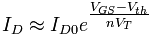 ,
,
here ID0 = current at VGS = Vth and slope factor n can be given by
n = 1 + CD / COX,
with CD = capacitance of the depletion layer and COX = capacitance of the oxide layer. In a long-channel device, there is no drain voltage dependence of the current once VDS > > VT, but as channel length is reduced drain-induced barrier lowering introduces drain voltage dependence that depends in a complex way upon the device geometry (for example, the channel doping, the junction doping and so on). Frequently, threshold voltage Vth for this mode is defined as the gate voltage at which a selected value of current ID0 occurs, for example, ID0 = 1 μA, which may not be the same Vth-value used in the equations for the following modes.
Some of the micropower analog circuits are designed to take advantage from the subthreshold conduction. By working in the weak-inversion region, the MOSFETs in these circuits deliver the highest possible transconductance-to-current ratio, namely: gm / ID = 1/ (nVT), almost that of the bipolar transistor.
The subthreshold I- V curve depends exponentially on the threshold voltage, introducing a strong dependence on any of the manufacturing variation which affects threshold voltage; for instance: variations in oxide thickness, junction depth, or body doping which change degree of drain-induced barrier lowering. The resulting sensitivity to fabricational variations complicates optimization for the leakage and performance.
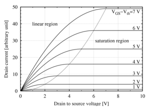
MOSFET drain current versus drain to source voltage for a number of values of VGS - Vth; the boundary in between saturation (active) and linear modes is indicated by upward curving parabola.
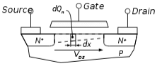
Cross section of a MOSFET operating in linear region; strong inversion region present even near drain
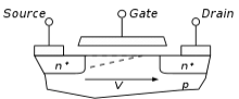
Cross section of a MOSFET operating in the saturation region; channel exhibits pinch- off near drain
Triode mode or linear region (also known as the ohmic mode.
When VGS > Vth and VDS < ( VGS - Vth )
Transistor is turned on, and a channel has been created which permits the current to flow in between the drain and the source. The MOSFET operates just like a resistor, controlled by gate voltage relative to the source and drain voltages both. The current from drain to source can be modeled as:
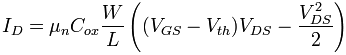
here μn is the charge carrier effective mobility, W is gate width, L is gate length and Cox is gate oxide capacitance per unit area. The transition from exponential subthreshold region to the triode region is not as sharp as equations suggest.
Saturation or active mode
When VGS > Vth and VDS > ( VGS - Vth )
The switch gets turned on, and a channel has been created, which allows current to flow in between the drain and source. As the drain voltage is higher than the gate voltage, the electrons spread out, and conduction is not by a narrow channel but by a broader, 2- or 3-dimensional current distribution extending away from interface and deeper in substrate. The onset of this region is also called as pinch-off to indicate the lack of channel region near drain. The drain current is now slightly dependent on drain voltage and controlled primarily by gate-source voltage, and modeled approximately as:
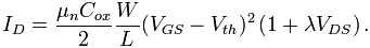
The additional factor involving λ, channel-length modulation parameter, models current dependence on the drain voltage because of the Early effect, or channel length modulation. According to equation, the key design parameter, MOSFET transconductance can be given by:
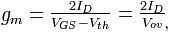
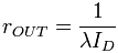
here the combination Vov = VGS - Vth is called as overdrive voltage. Another key design parameter is MOSFET output resistance rO can be given by:
Hear rout is inverse of gds  . VDS is the expression in the saturation region.
If λ is taken as zero, an infinite output resistance of device results which leads to unrealistic circuit predictions, particularly in analog circuits.
As the channel length becomes very short, these equations become quite inaccurate. New physical effects arise. For example, carrier transport in the active mode may become limited by velocity saturation. When velocity saturation dominates, the saturation drain current is nearly linear than quadratic in VGS. At shorter lengths even, carriers transport with near zero scattering, called as quasi ballistic transport. Additionally, the output current is affected by the drain-induced barrier lowering of threshold voltage.
Email based Electronics Devices and circuits assignment help - homework help at Expertsmind
Are you searching Electronics Engineering assignment help expert for help with Modes of operation of MOSFET questions? Modes of operation of MOSFET topic is not easier to learn without any external help? We at www.expertsmind.com offers free lecture notes for Electronics Devices and circuits assignment help and Electronics Devices and circuits homework help. Live tutors are available 24x7 hours for helping students in their Modes of operation of MOSFET related problems. We provide step by step Modes of operation of MOSFET question's answers with 100% plagiarism free content. We prepare quality content and notes for Modes of operation of MOSFET topic under Electronics Devices and circuits theory and study material. These are avail for subscribed users and they can get advantages anytime.
Why Expertsmind for assignment help
- Higher degree holder and experienced experts network
- Punctuality and responsibility of work
- Quality solution with 100% plagiarism free answers
- Time on Delivery
- Privacy of information and details
- Excellence in solving electronics engineering questions in excels and word format.
- Best tutoring assistance 24x7 hours