METHODS FOR TRANSISTOR BIASING
1. Fixed bias
2. Collector-to-base bias
3. Voltage divider bias
4. Emitter bias
1) Fixed bias (base bias):
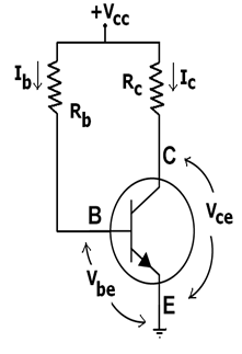
This form of biasing is called as base bias. In the example image on right, the single power source (for instance, a battery) is used for both the collector and base of transistor, separate batteries although can also be used.
In given circuit,
VCC = IBRB + Vbe
Therefore,
IB = (VCC - Vbe)/RB
For a given transistor, Vbe does not vary considerably during the usage. As VCC is of fixed value, on the selection of RB, base current IB is fixed. Hence this type of circuit is called as fixed bias type of circuit.
For given circuit, VCC = ICRC + Vce
Therefore,
Vce = VCC - ICRC
The common emitter current gain of the transistor is a significant parameter in circuit design, and is specified on data sheet for the particular transistor. It is denoted by β on this page.
Because IC = βIB
we can obtain IC as well. In this manner, operating point an be given as (VCE,IC) can be set for given transistor.
Merits:
- It is easy to shift the operating point anyplace in the active region by simply changing the base resistor (RB).
- A small number of components are mandatory.
Demerits:
- The collector current doesn't remain constant with variation in the temperature or power supply voltage. Hence the operating point is unstable.
- Changes in Vbe will change IB and cause RE to change. This in turn will change the gain of the stage.
- When the transistor is replaced with the other, the considerable change in value of β can be expected. Because of this change the operating point will shift.
2) Collector-to-base bias:
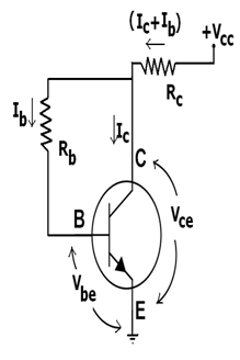
This configuration makes use negative feedback to prevent thermal runaway and stabilize the operating point. In this type of biasing, the base resistor RB is connected to collector instead of connecting it to the DC source VCC. So any thermal runaway will create a voltage drop across the RC resistor which will throttle the transistor's base current.
If Vbe is held constant and the temperature increases, then collector current Ic increases. But, a larger Ic causes voltage drop across resistor Rc to increase, which in turn decreases the voltage across the base resistor Rb. A lower base-resistor voltage drop decreases the base current Ib, which results in less collector current Ic. Because an increase in the collector current with temperature is opposed, the operating point is kept constant.
Merits:
- The circuit stabilizes the operating point against the variations in temperature and β (that is replacement of transistor)
Demerits:
- In the circuit, to keep Ic independent of β, the following condition should be met: which is the case when
- As β-value is fixed (and usually unknown) for the given transistor, this relation can be satisfied either by keeping Rc quite large or making Rb very low.
- If the value Rc is large, a high Vcc is necessary, which increases cost as well as precautions necessary while handling.
- If the value Rb is low, the reverse bias of collector-base region is small, which restrictions the range of collector voltage swing which leaves the transistor in active mode.
- The resistor Rb causes AC feedback, decreasing the voltage gain of the amplifier. This unwanted effect is a trade-off for the greater Q-point stability.
3)Voltage divider bias
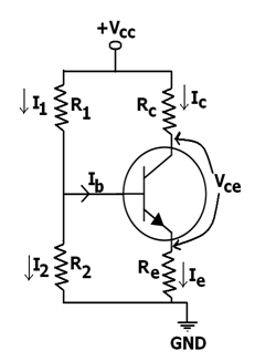
The voltage divider is formed by using the external resistors R1 and R2. The voltage across R2 forward biases the emitter junction. By the proper selection of resistors R1 and R2, the operating point of transistor can be made independent of β. In the circuit, voltage divider holds the base voltage constant independent of base current given that the divider current is large compared to the base current. But, even with the fixed base voltage, collector current varies with the temperature (for instance) so an emitter resistor is added to stabilize Q-point, like the above circuits with the emitter resistor.
Merits:
- unlike above circuits, only one DC supply is required.
- Operating point is independent of β variation.
- Operating point stabilized against the shift in temperature.
Demerits:
- As the value of β is fixed for the given transistor, this relation can be satisfied by keeping RE large enough, or making R1||R2 very low.
- If RE is of the large value, high VCC is required. This increases cost as well as safety measures necessary while handling this.
- If R1 || R2 is very low, one of the R1, or R2 is low, or both of them are low. A low R1 raises VB closer to VC, reducing available swing in the collector voltage, and checking how large RC can be made without driving transistor out of the active mode. The low R2 lowers Vbe, reducing allowed collector current. Lowering both the resistor values draws more current from power supply and lowers input resistance of the amplifier as seen in the base.
- The feedback AC and DC is caused by RE, which reduces AC voltage gain of the amplifier. A technique to avoid AC feedback while retaining feedback of DC is discussed below.
4)Emitter bias:
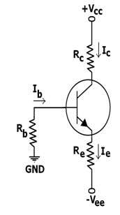
When a split supply (which is also known as dual power supply) is available, this biasing circuit is most effective, and provides zero bias voltage at emitter or collector for load. The negative supply V EE is used to forward-bias emitter junction through RE. The positive supply VCC is taken in use to reverse bias the collector junction. Only two resistors are required for the common collector stage and four resistors for common emitter.
As we know that, VB - VE = Vbe
If RB is small enough, base voltage will be approximately zero. Thus the emitter current becoms,
IE = (VEE - Vbe)/RE
The operating point is not dependent on β if RE >> RB/β
Merit:
Stability is good of operating point similar to that of voltage divider bias.
Demerit:
This type can only be used when a split (or dual) power supply is available to us.
Email based Electronics Devices and circuits assignment help - homework help at Expertsmind
Are you searching Electronics Engineering assignment help expert for help with Methods for Transistor Biasing questions? Methods for Transistor Biasing topic is not easier to learn without any external help? We at www.expertsmind.com offers free lecture notes for Electronics Devices and circuits assignment help and Electronics Devices and circuits homework help. Live tutors are available 24x7 hours for helping students in their Methods for Transistor Biasing related problems. We provide step by step Methods for Transistor Biasing question's answers with 100% plagiarism free content. We prepare quality content and notes for Methods for Transistor Biasing topic under Electronics Devices and circuits theory and study material. These are avail for subscribed users and they can get advantages anytime.
Why Expertsmind for assignment help
- Higher degree holder and experienced experts network
- Punctuality and responsibility of work
- Quality solution with 100% plagiarism free answers
- Time on Delivery
- Privacy of information and details
- Excellence in solving electronics engineering questions in excels and word format.
- Best tutoring assistance 24x7 hours