Low Pass Filter
A low pass filter lets the low frequencies to pass by the circuit whereas the high frequencies are severely attenuated or blocked. Figure (a) shows a low pass filter constructed by using a simple RC network. The output voltage, Vo is taken across capacitor.

Two different circuits used to construct a low pass filter Note that it is also possible to construct a low pass filter by using the RL combination as shown in the given
Figure Herein, the analysis is confined to RC circuit whereas the RL circuit can be observed in a similar manner.
The reactance of the capacitor is 1/jωC which will be used in mathematical analysis of the low pass
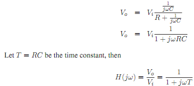
filter. To determine Vo, VDR (Chapter 3) can be applied as R and C are in series hence share the same current. Therefore

The output response of Equation 5.4 to a change in the input signal frequency is investigated.
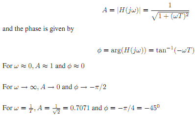
At low frequencies, ω ≈ 0, ∴ Vo ≈ Vi, i.e. most of Vi appears at output across capacitor. When
ω → ∞, Vo → 0, hence output voltage amplitude is attenuated that is very little of Vi appear at Vo at high frequencies. Therefore this circuit acts as a low pass filter. The frequency response can be inspected visually by plotting the amplitude and phase responses versus frequency. From
Equation, the amplitude response equation of the low pass filter can be derived as

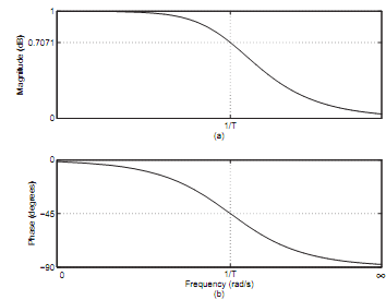
The response plots are shown in Figure

Frequency response of a low pass filter where (a) Amplitude response (b) Phase response
Bandwidth The frequency ω = 1/T is the cutoff frequency or the bandwidth of low pass filter. It is defined as the frequency range for which the amplitude A≥1/√2 Mathematically, the bandwidth of an RC low pass filter is given by

Clearly the bandwidth is user and problem dependent and can be adjusted simply by tuning the R and C parameters.
It is more common to express the gain, A of a circuit in Decibels (dB) units given by

which was originally developed as the logarithmic unit of power ratio i.e. 
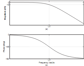
The amplitude plot in the Figure given below is redrawn in Figure with gain converted to dB versus logarithm of frequency. The phase response remains unchanged.
Some vital observations can be made by comparing the Figures given below
- Zero dB corresponds to a unity gain that is A = 1
- Negative dB corresponds to attenuation that is A < 1
- Positive dB corresponds to amplification that is A > 1

Figure: Frequency response of a low pass filter where (a) Amplitude response in dB (b) Phase response
• The bandwidth of the low pass filter is frequency range for which gain, A ≥ -3 dB
The -3 dB point is called as half power point as

Email based Low Pass Filter assignment help - Low Pass Filter homework help at Expertsmind
Are you finding answers for Low Pass Filter based questions? Ask Low Pass Filter questions and get answers from qualified and experienced Circuit Theory tutors anytime from anywhere 24x7. We at www.expertsmind.com offer Low Pass Filter assignment help -Low Pass Filter homework help and Circuit Theory problem's solution with step by step procedure.
Why Expertsmind for Circuit Theory assignment help service
1. higher degree holder and experienced tutors
2. Punctuality and responsibility of work
3. Quality solution with 100% plagiarism free answers
4. On Time Delivery
5. Privacy of information and details
6. Excellence in solving Circuit Theory queries in excels and word format.
7. Best tutoring assistance 24x7 hours