Implementation
A Schmitt trigger can be implemented with the simple tunnel diode, a diode with the "N"-shaped current-voltage characteristic in 1st quadrant. An oscillating input will cause the diode to move from one rising leg of "N" to other and back again as input crosses the rising and falling switching thresholds. But, the performance of this Schmitt trigger can be enhanced with transistor-based devices which make explicit use of positive feedback to implement the switching.
Comparator implementation
Schmitt triggers are commonly implemented using a comparator connected to have positive feedback (that is instead of the negative feedback used in operational amplifier circuits). For this circuit, the switching happens near ground, with the amount of hysteresis controlled by he resistances of R1 and R2:
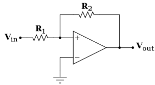
The comparator extracts sign of the difference between its 2 inputs. When non- inverting (+) input is at the higher voltage than inverting (-) input, comparator output switches to +VS, which is its high supply voltage. When non-inverting (+) input is at the lower voltage than inverting (-) input, comparator output switches to -VS, which is its low supply voltage. In this case, inverting (-) input is grounded, and so comparator implements sign function - its 2-state output (i.e., either high or low) always has the same sign as the continuous input at its non-inverting (+) terminal.
Due to the resistor network connecting Schmitt trigger input, the non-inverting (+) terminal of comparator, and comparator output, the Schmitt trigger behaves like a comparator which switches at a different point depending on whether the output of comparator is high or low. For negative inputs, output will be low, and for positive inputs, the output will be high, and so this is an implementation of a "non-inverting" Schmitt trigger. But, for intermediate inputs, the state of the output depends on the input and the output both. For instance, if the Schmitt trigger is currently in high state, the output will be at positive power supply rail (+VS). V+ is then a voltage divider between Vin and +VS. The comparator will switch when V+=0 (ground). Current conservation shows that this requires

and so Vin should drop below  to get the output to switch. Once the comparator output has switched to -VS, threshold becomes
  to switch back to high.
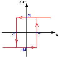
Characteristic hysteresis curve (which matches curve shown on a Schmitt trigger symbol)
So this circuit makes a switching band centered around zero, with trigger levels . The input voltage should rise above the top of the band, and then below the bottom of the band, for output to switch on and then back off. If R1 is zero or R2 is infinity (that is an open circuit), the band collapses to zero width, and it behaves as a standard comparator. The output characteristic is shown in the digram on the right. The value of threshold T is given by
  and the maximum value of output M is the power supply rail.
A practical Schmitt trigger configuration is shown as follows.
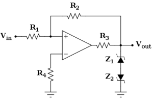
The output characteristic has the same shape exactly of the previous basic configuration, and the threshold values are also the same. On the other hand, in the earlier case, the output voltage was depending on power supply, while now it is defined by Zener diodes (which could also be replaced with the single double-anode Zener diode). In this configuration, the output levels can be modified by suitable choice of Zener diode, and these levels are resistant to power supply fluctuations (that is they increase the PSRR of the comparator). The resistor R3 is there to limit current through the diodes, and the resistor R4 minimizes input voltage offset caused by comparator's input leakage currents.
Email based Electronics Devices and circuits assignment help - homework help at Expertsmind
Are you searching Electronics Engineering assignment help expert for help with Implementation of Schmitt trigger questions? Implementation of Schmitt trigger topic is not easier to learn without any external help? We at www.expertsmind.com offers free lecture notes for Electronics Devices and circuits assignment help and Electronics Devices and circuits homework help. Live tutors are available 24x7 hours for helping students in their Implementation of Schmitt trigger related problems. We provide step by step Implementation of Schmitt trigger question's answers with 100% plagiarism free content. We prepare quality content and notes for Implementation of Schmitt trigger topic under Electronics Devices and circuits theory and study material. These are avail for subscribed users and they can get advantages anytime.
Why Expertsmind for assignment help
- Higher degree holder and experienced experts network
- Punctuality and responsibility of work
- Quality solution with 100% plagiarism free answers
- Time on Delivery
- Privacy of information and details
- Excellence in solving electronics engineering questions in excels and word format.
- Best tutoring assistance 24x7 hours