Digital filter design-The Butterworth filter:
Before going up design we produce below some of the substance relating filter descriptions to the filter order and the cut-off frequency.
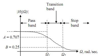
A type of magnitude response specification is given below. The magnitudes at the critical frequencies Ω1 and Ω2 are A and B, respectively. For explaining purposes we have

arbitrarily taken A = 0.707 (thus Ω1 is the cut-off frequency, but that need not be the case) and B = 0.25.
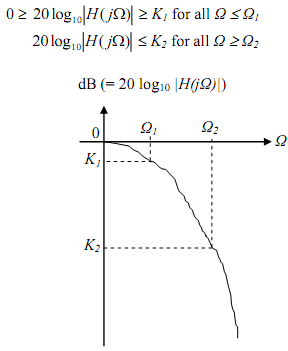
The log-magnitude specification is given below. Note that (20 log A) = K1 and (20 log B) = K2. Thus the analog filter needs are

With the resultant magnitude |H(jΩ)| shown by the Butterworth function,

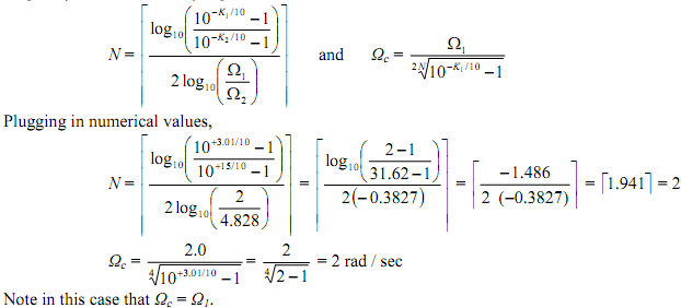
and using the equality condition at the critical frequencies in the given specifications the order, N, of the filter is shown by

The result is circulated to the next larger integer. For example, if N = 3.2 by the above computation then it is related up to 4, and the order of the needed filter is N = 4. In that a case the resulting filter could exceed the specification at both Ω1 and Ω2. The cut-off frequency Ωc is calculated from one of the two equations below.

The equation on the left will result in the properties being met similarly at Ω1 while the specification is preceded at Ω2. The equation on the right results in the specification being collected exactly at Ω2 and exceeded at Ω1.
Example Realize a digital low pass filter taking the bilinear transformation function to satisfy the following characteristics:
(a) A monotonic pass band and stop band
(b) -3.01 dB cut off frequency of 0.5p rad.
(c) Magnitude down at least 15 dB at 0.75p rad.

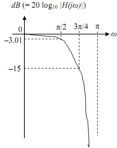
Note that the given frequencies are digital frequencies. The required frequency response is shown. We use bilinear transformation on an analog prototype.
Step 1 Pre-warp the critical digital frequencies ω1 = 0.5p and ω2 = 0.75p using T = 1 sec. That is, we find the analog frequencies ω´1 and ω´2 that correspond to ω1 and ω2:

Step 2 Design LP analog filter with critical frequencies ω1 and ω2 that satisfy

The Butterworth filter satisfies the monotonic property and has an order N and critical frequency Ωc determined by Eq. 3.16 and 3.17 of Ludeman

Therefore, the needed pre-warped, unit bandwidth, normalized, analog filter of order 2 using the Butterworth Table 3.1b (or the Butterworth circle) is
 (with a cut off frequency = 1 rad / sec)
Since we need a cut-off frequency of Ωc = 2 rad/sec, we next need the low pass to low pass transformation s → s/2 in order to take the cut-off frequency from 1 to 2 rad/sec.
 (with a cut-off frequency = 2 rad/sec.)
Step 3 Operating the bilinear transformation to Ha(s) with T = 1 will transform the pre-warped analog filter into a digital filter with the system function H(z) that can satisfy the provided digital requirements:

HW: calculate the difference equation. Plot | H (ejΩ) | and ∠H (e jw ) vs ω.
Email based Digital filter design-The Butterworth filter assignment help - Digital filter design-The Butterworth filter homework help at Expertsmind
Are you finding answers for Digital filter design-The Butterworth filter based questions? Ask Digital filter design-The Butterworth filter questions and get answers from qualified and experienced Digital signal processing tutors anytime from anywhere 24x7. We at www.expertsmind.com offer Digital filter design-The Butterworth filter assignment help -Digital filter design-The Butterworth filter homework help and Digital signal processing problem's solution with step by step procedure.
Why Expertsmind for Digital signal processing assignment help service
1. higher degree holder and experienced tutors
2. Punctuality and responsibility of work
3. Quality solution with 100% plagiarism free answers
4. On Time Delivery
5. Privacy of information and details
6. Excellence in solving Digital signal processing queries in excels and word format.
7. Best tutoring assistance 24x7 hours