Design of FIR digital filters - The Fourier series and windowing method
That function of filter design starts with the observation that the sinusoidal steady state transfer method of a digital filter is periodic in the sampling frequency. Since H(ω) is a periodic and continuous function of w we may elaborate it into a Fourier series. The resultant Fourier elements are the impulse response, h(n). The major disadvantage is that one may not easily specify in advance the same values for pass band and stop band attenuation/ripple levels, so it can be necessary to check various alternate designs to take the needed one.
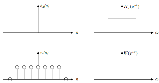
Suppose the ideal low pass filter with frequency response Hd(ejw) or Hd(ω) as given below. The subscript d defines that it is the ideal filter or desired.

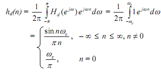
The impulse response is provided by

That is a non-causal infinite impulse response linear sequence. It is build by a finite impulse response sequence by calculating it symmetrically about n = 0; it is prepared causal by taking the truncated sequence to the right so that it executes at n = 0. The shifting results in a time delay and we will ignore it for now. The modified results in the sequence ht(n) where the subscript t defines truncation but we can ignore the subscript

Usually h(n) may be thought of as obtained by multiplying hd(n) with a window function w(n) as given
h(n) = hd(n).ω(n)
For the h(n) calculated by simple truncation as above the window function is a rectangular window provided by

Let H(ejw) and ω(ejw) show the Fourier transforms of h(n), hd(n) and w(n) respectively. Then the frequency response H (ejw) of the last filter is the convolution of Hd(ejw) and ω(ejw) Provided by

The convolution gives a smeared type of the ideal low pass filter. In another words, H (ejw) is a smeared version of H(ejw) . Usually, the wider the basic lobe ofW (ejw) , the more illustrating or smearing, whereas the narrower the basic lobe (larger N), the closer Hd(ejw ) tends to H(ejw ) .
For any arbitrary part the transition band of the filter is calculated by the width of the basic lobe of the window. The side lobes of the window gives ripples in both stop band and pass band.
Usually, we are right with a trade-off of creating N large enough so that smearing is minimum, yet the value of filter coefficients (= N) is not too big for a reasonable execution. Some normally used windows are the Bartlett (triangular), rectangular, Hanning, Hamming, Kaiser Windows and Blackman.

Email based Design of FIR digital filters assignment help - Design of FIR digital filters homework help at Expertsmind
Are you finding answers for Design of FIR digital filters based questions? Ask Design of FIR digital filters questions and get answers from qualified and experienced Digital signal processing tutors anytime from anywhere 24x7. We at www.expertsmind.com offer Design of FIR digital filters assignment help -Design of FIR digital filters homework help and Digital signal processing problem's solution with step by step procedure.
Why Expertsmind for Digital signal processing assignment help service
1. higher degree holder and experienced tutors
2. Punctuality and responsibility of work
3. Quality solution with 100% plagiarism free answers
4. On Time Delivery
5. Privacy of information and details
6. Excellence in solving Digital signal processing queries in excels and word format.
7. Best tutoring assistance 24x7 hours