Common Base Amplifier

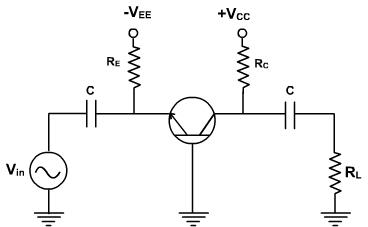
The common base amplifier circuit is given in the figure 1. The VEE source forward biases emitter diode and VCC source reverse biased collector diode. The AC source vin is connected to emitter through a coupling capacitor such that it blocks DC. This ac voltage produces small variation in currents and voltages. The load resistance RL is connected to collector through coupling capacitor also so the variation in collector base voltage will be observed across RL.
The DC equivalent circuit can be obtained by reducing all the AC sources to zero Figure 1 and opening all the capacitors. The dc collector current is same as IE and VCB can be given by
VCB = VCC - IC RC.
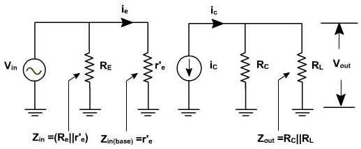
The current and voltage fix Q point. The AC equivalent circuit can be obtained by reducing all the DC sources to zero and shorting all the coupling capacitors. r'e represents AC resistance of the diode as shown in the figure 2.

Figure 2
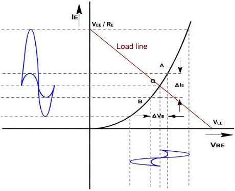
Figure 3, shows diode curve relating IE and VBE. In absence of the AC signal, the transistor operates at Q point. When the AC signal is applied, the emitter current and voltage also change. If signal is small, the operating point swings sinusoidally about Q point.

Fig .3
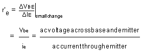
If AC signal is small, the points A and B are near to Q, and arc A B can be approximated by a straight line and diode appears to be the resistance which is given by

If input signal is small, input voltage and current will be sinusoidal in nature but if the input voltage is large then the current will no longer be sinusoidal due to the non linearity of diode curve. The emitter current is elongated on positive half cycle and compressed on the negative half cycle. Hence output will also be distorted.
r'e is the ratio of ΔVBE and Δ IE and its value depends upon location of the Q. Higher up the Q point small will be value of r' e because same change in VBE produces the large change in IE. The slope of curve at Q decides the value of r'e. From the calculation it can be proved that
r'e = 25mV / IE
Proof-
Generally the current through a diode can be given by

Where q is the charge on electron, V is drop across diode, T is temperature and K is a constant.
On differentiating with respect to V, we get,

The value of (q / KT) at temperature 25°C is approximately 40. Therefore,

or,


To a close approximation small changes in the collector current equal the small changes in emitter current. In AC equivalent circuit, the current =iC' is shown upward as if =ie' increases, then =iC' also increases in same direction.
Email based Electronics Devices and circuits assignment help - homework help at Expertsmind
Are you searching Electronics Engineering assignment help expert for help with Common Base Amplifier questions? Common Base Amplifier topic is not easier to learn without any external help? We at www.expertsmind.com offers free lecture notes for Electronics Devices and circuits assignment help and Electronics Devices and circuits homework help. Live tutors are available 24x7 hours for helping students in their Common Base Amplifier related problems. We provide step by step Common Base Amplifier question's answers with 100% plagiarism free content. We prepare quality content and notes for Common Base Amplifier topic under Electronics Devices and circuits theory and study material. These are avail for subscribed users and they can get advantages anytime.
Why Expertsmind for assignment help
- Higher degree holder and experienced experts network
- Punctuality and responsibility of work
- Quality solution with 100% plagiarism free answers
- Time on Delivery
- Privacy of information and details
- Excellence in solving electronics engineering questions in excels and word format.
- Best tutoring assistance 24x7 hours