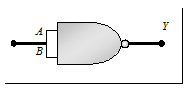
(1) The 'NAND' gate: From 'AND' and 'NOT' gate

Boolean expression and truth table: 
|
A
|
B
|
Y¢ = A × B
|
Y
|
|
0
|
0
|
0
|
1
|
|
0
|
1
|
0
|
1
|
|
1
|
0
|
0
|
1
|
|
1
|
1
|
1
|
0
|
(2) The 'NOR' gate: From 'OR' and 'NOT' gate
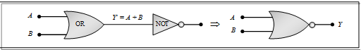
Boolean expression and truth table: 
|
A
|
B
|
Y¢ = A + B
|
Y
|
|
0
|
0
|
0
|
1
|
|
0
|
1
|
1
|
0
|
|
1
|
0
|
1
|
0
|
|
1
|
1
|
1
|
0
|
(3) The 'XOR' gate: From 'NOT', 'AND' and 'OR' gate. Called as exclusive OR gate.
It may be noted that if both the inputs of the XOR gate is 1, then the output is 0.
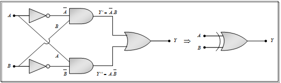
Boolean expression and truth table: Y = A Å B = 
|
A
|
B
|
Y
|
|
0
|
0
|
0
|
|
0
|
1
|
1
|
|
1
|
0
|
1
|
|
1
|
1
|
0
|
(4) The exclusive nor (XNOR) gate: XOR + NOT XNOR
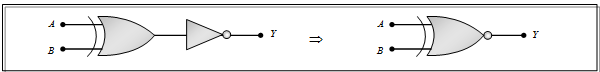
Boolean expression: Y = A ¤ B =
Logic Gates Using 'NAND' Gate
The NAND gate is the building block of the digital electronics. All the logic gates like the OR, the AND and the NOT can be constructed from the NAND gates.
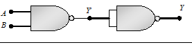
(1) Construction of the ' NOT' gate circuit from the ' NAND' gate
(i) When both the inputs (A and B) of the NAND gate are joined together then it works as the NOT gate.
(ii) Truth table and logic symbol
|
Input
|
Output
|
|
A = B
|
Y
|
|
0
|
1
|
|
1
|
0
|
(2) Construction of the 'AND' gate from the 'NAND' gate:
(i) When the output of the NAND gate is given to the input of the NOT gate (made from the NAND gate), then the final logic circuit behaves as the AND gate
(ii) Truth table and logic symbol
|
A
|
B
|
Y¢
|
Y
|
|
0
|
0
|
1
|
0
|
|
0
|
1
|
1
|
0
|
|
1
|
0
|
1
|
0
|
|
1
|
1
|
0
|
1
|
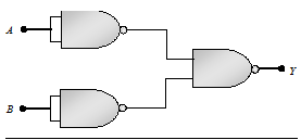
(3) Construction of the 'OR' gate by the 'NAND' gate
(i) When the outputs of two NOT gates (obtained from the NAND gate) is given to the inputs of the NAND gate, the final logic circuit behaves as the OR gate
(ii) Truth table and logic symbol
|
A
|
B
|
|
|
Y
|
|
0
|
0
|
1
|
1
|
0
|
|
0
|
1
|
1
|
0
|
1
|
|
1
|
0
|
0
|
1
|
1
|
|
1
|
1
|
0
|
0
|
1
|
Email based Physics assignment help - homework help at Expertsmind
Are you searching physics expert for help with Combination of Logic Gates questions? Combination of Logic Gates topic is not easier to learn without external help? We at www.expertsmind.com offer finest service of Physics assignment help and physics homework help. Live tutors are available for 24x7 hours helping students in their Combination of Logic Gates related problems. We provide step by step Combination of Logic Gates question's answers with 100% plagiarism free content. We prepare quality content and notes for Combination of Logic Gates topic under physics theory and study material. These are avail for subscribed users and they can get advantages anytime.
Why Expertsmind for assignment help
- Higher degree holder and experienced experts network
- Punctuality and responsibility of work
- Quality solution with 100% plagiarism free answers
- Time on Delivery
- Privacy of information and details
- Excellence in solving physics queries in excels and word format.
- Best tutoring assistance 24x7 hours