stable Multivibrator
Introduction
Since the use of one capacitor prevents circuit from remaining stable in one of the 2 possible states of it, it seems likely that with both sides coupled this way circuit will be unable to remain stable in either state. That is actually the case, and in this experiment we will construct and demonstrate the circuit.
Schematic Diagram
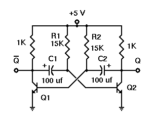
As shown in diagram here, the astable multivibrator simply extends modification which converted the bistable multivibrator to a monostable version of circuit. Now, both the transistors are coupled to each other by capacitors. Whichever transistor is off at any moment cannot remain off indefinitely; its base will become forward biased as that capacitor charges towards +5 volts. Once that occurs, that transistor will turn on, thus turning the other one off.
3-6 Figure 3-3.-Astable Multivibrator.
When an input signal to one amplifier is large enough, the transistor can be driven into cutoff, and its collector voltage will be almost V CC. But, when the transistor is driven into the saturation, its collector voltage will be around 0 volts. A circuit which is designed to go rapidly from cutoff to saturation will produce a square or rectangular wave at its output. The principle is used in multivibrators. Multivibrators can be classified according to the number of steady states of the circuit. A steady state exists when the circuit operation is constant; that is, one transistor remains in conduction and other remains cut off until an external signal is applied. The 3 types of multivibrators are the MONOSTABLE, ASTABLE, and BISTABLE. The circuit has no stable state. With no external signal applied, transistors switch alternately from cutoff to saturation at a frequency determined by the RC time constants of the coupling circuits. The monostable circuit has 1 stable state; 1 transistor conducts while the other is cut off. A signal should be applied to change this condition. After some time, determined by internal RC components, circuit will return to the original condition where it remains until the next signal arrives. Bistable multivibrator has the 2 stable states. It remains in the stable states until the trigger is applied. It then FLIPS to the other stable condition and remains there till the other trigger is applied. The multivibrator then changes back to its first stable state.
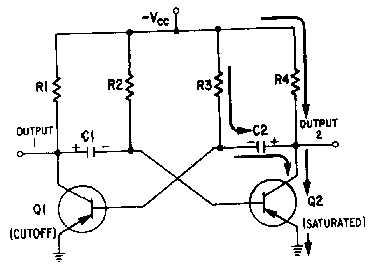
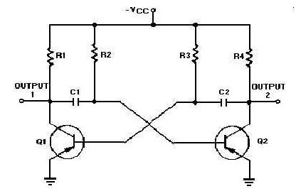
3-8 Figure 3-5.-Astable multivibrator. Figure 3-6.-Astable multivibrator. (Q2 saturated).
Notice the figure 3-6 is mirror image of the figure 3-4. In the figure 3-6 the left side of capacitor C2 becomes more negative at the rate determined by the time constant R3C2. As the left side of C2 becomes negative, the base of Q1 also becomes negative. When base of Q1 becomes negative enough to allow Q1 to conduct, Q1 will again go into the saturation. The change resulting in voltage at output 1 will cause Q2 to return to the cutoff state. See the output waveform from transistor Q2, as given in figure 3-7. The output voltage (from output of the multivibrator) alternates from approximately 0 volts to V approximately CC, remaining in each state for a definite period of time. The time may range from a microsecond to as much as a second or two. V In some applications, the time period of higher voltage ( CC) and the time period of lower voltage (0 volts) will be equal. Other applications require differing higher- and lower-voltage times. For instance, timing and gating circuits often have different
pulse widths as shown in figure 3-8
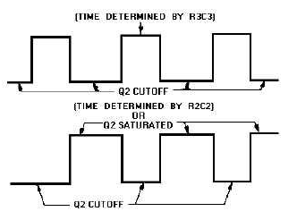
3-9 Figure 3-7.-Square wave output from Q2. Figure 3-8.-Rectangular waves.
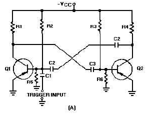
FREQUENCY STABILITY.-Some astable multivibrators should have a high degree of frequency stability. One way to achieve a high degree of frequency stability is to apply triggers. The circuit will remain in this condition as long as the base voltage of Q2 is positive. The length of time the base of Q2 will remain positive can be determined by C3, R3, and R6. Observe parallel paths for the C3 to discharge.
Figure 3-9A.-Triggered astable multivibrator and output.
See (B) of figure 3-9 shows waveforms associated with the circuit. Some times T1, Q2 comes out of cutoff and goes into the saturation. Q1 is made to come out of saturation and is cut off. The base voltage waveform of Q1 shows the positive potential which is holding Q1 at cutoff. This voltage would hold Q1 normally at cutoff until a point between T2 and T3. Q1 goes into the saturation and Q2 is caused to cut off. This repeats each time the trigger (T2, T4, T6) is applied.
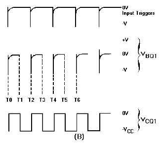
Figure 3-9B.-Triggered astable multivibrator and output.
The prt of the input triggers should be shorter than natural free-running prt of astable multivibrator, or trigger prf should be slightly higher than the free-running prf of circuit. This is to make certain that the triggers control the prt of output.
Email based Electronics Devices and circuits assignment help - homework help at Expertsmind
Are you searching Electronics Engineering assignment help expert for help with Astable Multivibrator questions? Astable Multivibrator topic is not easier to learn without any external help? We at www.expertsmind.com offers free lecture notes for Electronics Devices and circuits assignment help and Electronics Devices and circuits homework help. Live tutors are available 24x7 hours for helping students in their Astable Multivibrator related problems. We provide step by step Astable Multivibrator question's answers with 100% plagiarism free content. We prepare quality content and notes for Astable Multivibrator topic under Electronics Devices and circuits theory and study material. These are avail for subscribed users and they can get advantages anytime.
Why Expertsmind for assignment help
- Higher degree holder and experienced experts network
- Punctuality and responsibility of work
- Quality solution with 100% plagiarism free answers
- Time on Delivery
- Privacy of information and details
- Excellence in solving electronics engineering questions in excels and word format.
- Best tutoring assistance 24x7 hours