Applications
Schmitt triggers are used in open loop configurations for the noise immunity and closed loop positive feedback configurations to execute multivibrators.
Noise immunity
One application of a Schmitt trigger is to increase the noise immunity in a circuit with only a single input threshold. With only one input threshold, a noisy input signal near the threshold could cause output to switch quickly back and forth from noise alone. A noisy Schmitt Trigger input signal near 1 threshold can cause only 1 switch in output value, after which it would have to move beyond other threshold in order to cause another switch.
For instance, in Fairchild Semiconductor's QSE15x the family of infrared photosensors, an amplified infrared photodiode generates an electric signal which switches frequently between absolute lowest value and absolute highest value. This signal is then low-pass filtered to form the smooth signal which rises and falls corresponding to relative amount of time the switching signal is on and off. The filtered output passes to input of the Schmitt trigger. The average effect is that the output of Schmitt trigger passes only from low to high after a received infrared signal excites photodiode for longer than some known delay, and once Schmitt trigger is high, it only moves low after infrared signal stops to excite the photodiode for longer than a similar known delay. While the photodiode is prone to spurious switching because of noise from the environment, the delay added by filter and Schmitt trigger ensures that output only switches when there is an input stimulating the device.
Devices that include a built-in Schmitt trigger
As discussed in the example above, the Fairchild Semiconductor QSE15x family of photosensors use a Schmitt trigger internally for noise immunity. Schmitt triggers are common in many switching circuits for similar reasons (e.g., for switch debouncing).
The following 7400 series devices include a Schmitt trigger on their input or on each of their inputs:
- 7413: Dual Schmitt trigger 4-input NAND Gate
- 7414: Hex Schmitt trigger Inverter
- 7418: Dual Schmitt trigger 4-input NAND Gate
- 7419: Hex Schmitt trigger Inverter
- 74121: Monostable Multivibrator with Schmitt Trigger Inputs
- 74132: Quad 2-input NAND Schmitt Trigger
- 74221: Dual Monostable Multivibrator with Schmitt Trigger Input
- 74232: Quad NOR Schmitt Trigger
- 74310: Octal Buffer with Schmitt Trigger Inputs
- 74340: Octal Buffer with Schmitt Trigger Inputs and three-state inverted outputs
- 74341: Octal Buffer with Schmitt Trigger Inputs and three-state noninverted outputs
- 74344: Octal Buffer with Schmitt Trigger Inputs and three-state noninverted outputs
- 74(HC/HCT)7541 Octal Buffer with Schmitt Trigger Inputs and Three-State Noninverted
Outputs
- SN74LV8151 is a 10-bit universal Schmitt-trigger buffer with 3-state outputs
A number of 4000 series devices include a Schmitt trigger on inputs, for example:
- 4093: Quad 2-Input NAND
- 40106: Hex Inverter
- 14538: Dual Monostable Multivibrator
- 4020: 14-Stage Binary Ripple Counter
- 4024: 7-Stage Binary Ripple Counter
- 4040: 12-Stage Binary Ripple Counter
- 4017: Decade Counter with Decoded Outputs
- 4022: Octal Counter with Decoded Outputs
- 4093: Quad Dual Input NAND gate
Dual Schmitt input configurable single-gate CMOS logic, AND, OR, XOR, NAND, NOR, XNOR
- NC7SZ57 Fairchild
- NC7SZ58 Fairchild
- SN74LVC1G57 Texas Instruments
- SN74LVC1G58 Texas Instruments
Use as an oscillator
The Schmitt trigger is a bistable multivibrator, and it can also be used to implement another type of multivibrator, relaxation oscillator. This can be achieved by connecting a single resistor-capacitor network to the inverting Schmitt trigger - the capacitor connects in between the input and ground and resistor connects in between the output and the input. The output will be a continuous square wave the frequency of which depends on the values of R and C, and the threshold points of Schmitt trigger. As multiple Schmitt trigger circuits can be provided by a single integrated circuit (for example the 4000 series CMOS device type 40106 contains 6 of them), a spare section of IC can be quickly pressed into the service as a reliable and simple oscillator with only 2 external components.
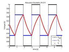
The Output and capacitor waveforms for the comparator-based relaxation oscillator.
For instance, the comparator-based implementation of the relaxation oscillator is shown below.
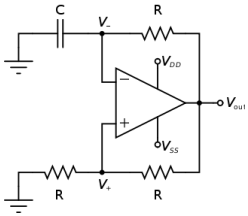
Here, the comparator-based Schmitt trigger is taken in use in its inverting configuration. That is, input and ground are swapped from Schmitt trigger shown above, and so negative signals correspond to the positive output and positive signals correspond to a negative output. In addition, slow negative feedback is added with the RC network. The result, which is shown on right, is that the output oscillates automatically from VSS to VDD as capacitor charges from one Schmitt trigger threshold to other.
The UJT as name implies, is characterized by a single PN junction. It has negative resistance characteristic which makes it useful in oscillator circuits.
The symbol for UJT is shown in the figure 1. The UJT is having 3 terminals base1 (B1), base2 (B2) and emitter (E). The UJT is made up of the N-type silicon bar which behaves as the base as shown in the figure 2. It is lightly doped. A P-type impurity is introduced into base, producing a single PN junction called as emitter. The PN junction exhibits properties of the conventional diode.
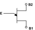
Figure 1
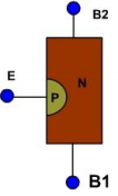
Figure 2
A complementary UJT is produced by a P-type base and N-type emitter. Except the polarity of voltage and current the characteristic is similar to those of the conventional UJT.
A simplified equivalent circuit for UJT is shown in the figure 3. VBB is a source of biasing voltage connected in between B2 and B1. When emitter is open, total resistance from B2 to B1 is simply resistance of the silicon bar, this is called as the inter base resistance RBB. Since the N-channel is slightly doped, thus RBB is relatively high, normally 5 to 10K ohm. RB2 is the resistance in between B2 and point =a', while RB1 is resistance from point =a' to B1, thus the interbase resistance RBB is
RBB = RB1 + RB2
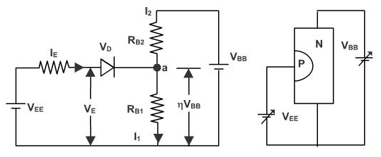
Figure 3
Email based Electronics Devices and circuits assignment help - homework help at Expertsmind
Are you searching Electronics Engineering assignment help expert for help with Applications of Schmitt trigger questions? Applications of Schmitt trigger topic is not easier to learn without any external help? We at www.expertsmind.com offers free lecture notes for Electronics Devices and circuits assignment help and Electronics Devices and circuits homework help. Live tutors are available 24x7 hours for helping students in their Applications of Schmitt trigger related problems. We provide step by step Applications of Schmitt trigger question's answers with 100% plagiarism free content. We prepare quality content and notes for Applications of Schmitt trigger topic under Electronics Devices and circuits theory and study material. These are avail for subscribed users and they can get advantages anytime.
Why Expertsmind for assignment help
- Higher degree holder and experienced experts network
- Punctuality and responsibility of work
- Quality solution with 100% plagiarism free answers
- Time on Delivery
- Privacy of information and details
- Excellence in solving electronics engineering questions in excels and word format.
- Best tutoring assistance 24x7 hours