Steam Jet Refrigeration System
Such system, also termed as a flash cooling system, is usually used for chilling the water. The system turns out to be an economical proposition, in comparison to the VCRS, in such cases where steam, to be employed in the ejector of the system, is available inexpensively in large amounts.
The figure shown below illustrates the schematic diagram of a steam jet refrigeration system.
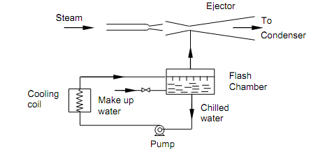
Figure: Steam Jet Refrigeration System
The water to be chilled is sprayed in the flash chamber. This chamber is fine insulated and sustained at low pressure with the help of the steam ejector that constantly eliminates the water vapor flashing in the chamber. Since the chamber is insulated, the energy needed for vaporizing a portion of spray water has to be supplied by the non- vaporizing liquid portion. Therefore the temperature of liquid water in the flash chamber reduces to provide the needed chilled water. The chilled water is pumped out to an exterior heat exchanger, via the cooling coils, where it cools the air to be conditioned. The water from cooing coils is again passed to the flash chamber. Since water vapor is being continuously eliminated from the flash chamber there is requirement for supplying make up water to the system. The steam from ejector is condensed in a large condenser that is cooled by water from the local source. The condenser is sustained at the required low pressure, generally sub-atmospheric, by wet and dry pumps.
Example:
The ideal wet compression refrigeration cycle, with R-12 as the refrigerant, functions among an evaporator temperature of – 10oC and a condenser temperature of 40oC. Compute the following:
(a) Refrigerating effect,
(b) Compressor work, and
(c) COP.
Solution:
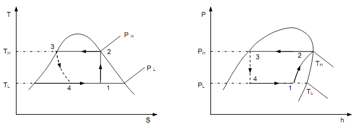
The system is functioning on the cycle in figure above, here TH = 40oC and TL = − 10oC. The needed properties of R-12 can be read from the Liquid-Vapor saturation, pressure table
h2 = hg at 40oC = 203.05 kJ/kg
h3 = hf at 40oC = 74.53 kJ/kg
h4 = h3 = 74.53 kJ/kg
To compute the value of h1:
s2 = sg at 40oC = 0.6820 = s1.
But,
s1 = [(1 – x1) sf + x1 sg] at – 10oC
∴ 0.6820 = (1 – x1) x 0.1079 + x1 x 0.7014 or x1 = 0.967
Now,
h1 = [(1 – x1) hf + x1 hg] at -10oC
h1 = 0.033 x 26.85 + 0.967 x 183.06 = 177.9 kJ/kg
(a) Ref. effect = h1 – h4 = 177.9 – 74.53 = 103.37 KJ/kg
(b) Comp. work = h2 – h1 = 203.05 – 177.9 = 25.15 KJ/kg
(c)
Solution:
The system is functioning on the cycle in figure above, here TH = 40oC and TL = − 10oC. The needed properties of R-12 can be read from the Liquid-Vapor saturation, pressure table
h2 = hg at 40oC = 203.05 kJ/kg
h3 = hf at 40oC = 74.53 kJ/kg
h4 = h3 = 74.53 kJ/kg
To compute the value of h1:
s2 = sg at 40oC = 0.6820 = s1.
But,
s1 = [(1 – x1) sf + x1 sg] at – 10oC
∴ 0.6820 = (1 – x1) x 0.1079 + x1 x 0.7014 or x1 = 0.967
Now,
h1 = [(1 – x1) hf + x1 hg] at -10oC
h1 = 0.033 x 26.85 + 0.967 x 183.06 = 177.9 kJ/kg
(a) Ref. effect = h1 – h4 = 177.9 – 74.53 = 103.37 KJ/kg
(b) Comp. work = h2 – h1 = 203.05 – 177.9 = 25.15 KJ/kg
(c)
COP= Ref.effect/Comp. effect =103.37/25.15=4.11