Feedback Control System Block Diagram:
Figure shows basic elements of a feedback control system as represented by a block diagram. The functional relationships between these elements are easily seen. An important factor to remember is that the block diagram represents flowpaths of control signals, but does not represent flow of energy through the system or process.
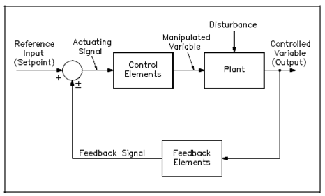
Figure: Feedback Control System Block Diagram
Below are various terms related along with the closed-loop block diagram.
The plant is the system or procedure by that a particular quantity or condition is controlled. This is also known as the controlled system.
The control elements are components required to produce the appropriate control signal applied to the plant. These components are also known as the "controller."
The feedback elements are components required to identify the functional relationship among the feedback signal and the controlled outcome.
The reference point is an external signal applied to the summing point of the control system to cause the plant to generate a specified action. That signal represents the desired value of a controlled variable and is also known as the "setpoint."